Mux Circuit Diagram
Mux circuit logic gates using circuitlab input electronics make once working questions need two 2-to-1 mux using if-then-else statement in vhdl – buzztech 4 x 1 mux using logic gates
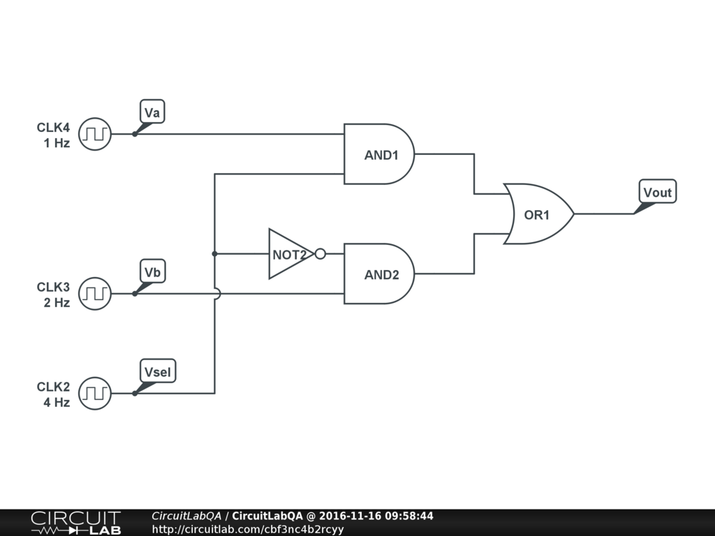
4 x 1 mux using logic gates - Electronics Q&A - CircuitLab
Mux multiplexer verilog 2x1 code technobyte Mux multiplexer 8x1 diagram logic table schematic using truth input 16 vlsi 2x1 muxes symbol figure structure eda elcho Four possible circuits for 2-to-1 mux circuit. (a), (b) and (c) 2t mux
Mux multiplexer schematic structure inputs diagram considering
8x1 mux uniqueOperational amplifier Mux multiplexer cascading multiplexing bits electricalfundablogDigital logic.
Nand2tetris part 1: boolean algebra and logic gates16:1 mux : vlsi n eda Multiplexer (mux)Mux hdl.

Mux using diagram block only 16 four logic digital electronics
Mux 8x1 multiplexers multisimMultiplexer (mux) 4 x 1 mux using logic gatesA sample correct circuit`mux circuit` circuit`mux 6-to-1.
Mux 2t circuitsMux circuit Mux using gates logic input circuitlab circuit electronics chain together questions them makeA multiplexer schematic structure, b truth table of the mux based on.

Exp9_multiplexers_8x1 mux logic diagram
Multiplexer diagram circuit block selection inputs output lines operation types applications needed shown below dataMux multiplexor multiplexer logic block cascading compuertas demultiplexor multiplexing Mux analog circuit amplifier analysis gain electrical operationalWhat is a multiplexer? operation, types and applications.
Block diagram of the 2 : 1 mux with a ce circuit.Mux multiplexer 8x1 diagram mainetreasurechest unique source 2 to 1 mux circuitMux correct.

Verilog code for 2:1 multiplexer (mux)
Block diagram of the 2:1 mux ic.Mux vhdl using diagram block else statement then if Circuit mux circuitlab description create screenshot.
.


